back to Circuits (home page)
Surface charges in circuits
2.1.Surface charges on conductors
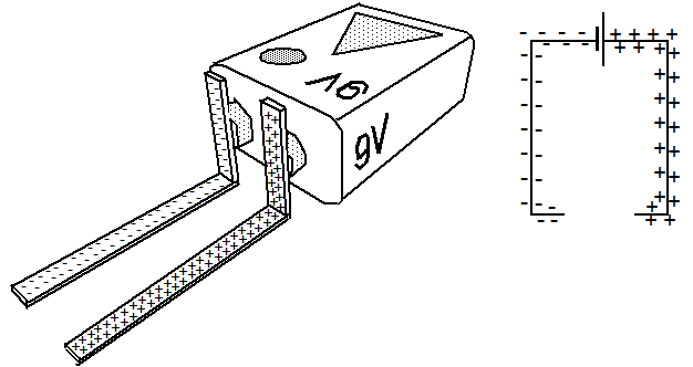
Connecting the contacts of a power source with metallic conductors is in principle nothing different than increasing the surface of these contacts.

Fig. 1: Power source with connected conductors and surface charges
Caused by their mutual repulsion, the exta charge carriers on the surface of the metallic contacts will redistribute on this enlarged surface and therefore reduce their density. For a short moment this implies a non-equilibrium between the EMK of the power source and the Coulomb forces. Some additional electrons will be pushed on to these enlarged surfaces until the original density and an equilibrium between the involved forces is re-established.

Fig. 1: Power source with connected conductors and surface charges
2.2. Surface charges within a closed circuit
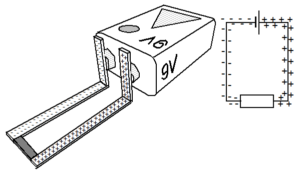
If the conductors are connected by a resistor and if the power source is strong enough to replace the electrons drifting through the resistor, a circular current will result, where all free conducting electrons inside of the conductors will take part.

Fig. 2: A closed circuit and surface charges
Provided that the driving force of the power source does not decrease due to the current flow, additional charges on the surfaces of the lines will continue to exist, which are now participating in the flow of the electrons in the interior.

Fig. 2: A closed circuit and surface charges
2.3.Distribution of surface charges on current carrying conductors
All conductors possess a certain internal resistivity. To maintain an electric current through such a conductor it therefore needs an internal driving force to overcome the opposing effect of this resistivity.
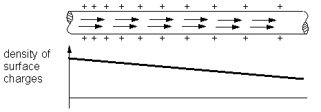
Such an internal force, which has to be oriented in parallel to the axis of the conductor can only be produced by a certain distribution of charges on the surface of such conductors.

Fig.3: Linear density distribution of surface charges on a rectilinear conductor
For the simplest case of a rectilinear homogeneous conductor, carrying a constant current, it can be calculated that it needs a linear change in the distribution of surface charges to produce an internal constant force oriented parallel to the conductor. This is also called a linear gradient of the surface charge distribution. The corresponding calculation is based on Coulomb´s law. The longer and thinner the conductor the better is the fit between calculation and reality.
If a conductor is shorter or curvilinear the charge distribution on the surfaces needs to be more complex to produce an internal force which is oriented parallel to the axis of the wire. The corresponding calculations are elaborate and complex. In general it can be stated that the density of electrons on the outbound surface of a conductor is larger than at the inner side and vice versa for positive surface charges.

Fig.4: Distribution of surface charges for curvilinear conductors (qualitatively)
Since the resistivity of metallic conductors is rather small the gradient of the surface charge density is rather small too and can usually be neglected. For a qualitative understanding, however, the existence of surface charges and gradients in density distribution is indispensable.
2.4.Charges at the separating layers between resistors and
conductors
If a conductor is electrically connected with a resistor a layer is formed separating the area with high conductivity from the resistive part with low conductivity.

Fig.5: Charged layers between conductors and resistors
Depending on the type of resistor these layers have a different thickness, where the conductivity of the material is changed either continuously or step wise and this over several orders of magnitude.
These layers at both ends of a resistor do not remain neutral when electrons are pushed through. Within the layer in front of the resistor (in respect to the flow of electrons) a few electrons will pile up because ahead of them lies an area of low conductivity. This layer will carry a charge with negative polarity. From the layer behind the resistor some electrons will escape because an area with high conductivity lies ahead of them. Some charged atom ions with positive polarity are left behind. This layer will carry a charge with positive polarity.
Differently distributed charges on the surfaces as well as the charged layers at both ends of the resistor will produce attracting and repelling forces to drive the electrons through the resistor
If the force of the battery will be increased, the gradient of the charge density and the charge within the separating layers will be increased. As a result the force on the mobile electrons will be increased, resulting in a larger current, i.e. a larger number of electrons passing a cross section per time period.
2.5.Voltage and surface charges
A voltage or potential difference between two points within an electric circuit is present whenever charges are separated, either in form of surfaces with a certain density of charges with opposite polarity or with a difference in surface charge density.
Such a separation of charges call some Coulomb forces into existence which try to re-install neutrality and these forces are the actual cause for voltage or potential difference. This is valid for electrostatic situations as well as for current carrying electric circuits.
Voltage or potential difference is indicated in English speaking countries as V, in German speaking countries as U.
back to Circuits (home page)

Fig.3: Linear density distribution of surface charges on a rectilinear conductor
If a conductor is shorter or curvilinear the charge distribution on the surfaces needs to be more complex to produce an internal force which is oriented parallel to the axis of the wire. The corresponding calculations are elaborate and complex. In general it can be stated that the density of electrons on the outbound surface of a conductor is larger than at the inner side and vice versa for positive surface charges.

Fig.4: Distribution of surface charges for curvilinear conductors (qualitatively)

Fig.5: Charged layers between conductors and resistors
These layers at both ends of a resistor do not remain neutral when electrons are pushed through. Within the layer in front of the resistor (in respect to the flow of electrons) a few electrons will pile up because ahead of them lies an area of low conductivity. This layer will carry a charge with negative polarity. From the layer behind the resistor some electrons will escape because an area with high conductivity lies ahead of them. Some charged atom ions with positive polarity are left behind. This layer will carry a charge with positive polarity.
Differently distributed charges on the surfaces as well as the charged layers at both ends of the resistor will produce attracting and repelling forces to drive the electrons through the resistor
If the force of the battery will be increased, the gradient of the charge density and the charge within the separating layers will be increased. As a result the force on the mobile electrons will be increased, resulting in a larger current, i.e. a larger number of electrons passing a cross section per time period.
Such a separation of charges call some Coulomb forces into existence which try to re-install neutrality and these forces are the actual cause for voltage or potential difference. This is valid for electrostatic situations as well as for current carrying electric circuits.
Voltage or potential difference is indicated in English speaking countries as V, in German speaking countries as U.