back to Home
2. Simulation Tool Java-xyZET
General Information
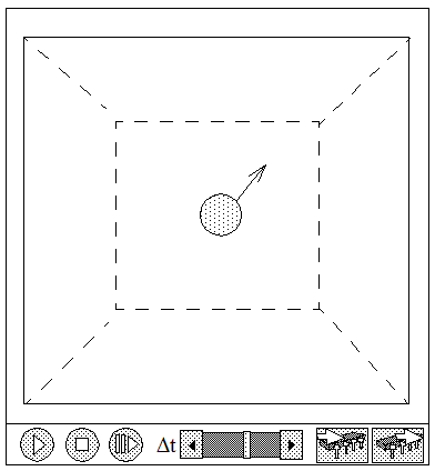
Fig. 2.1.: Main simulation window with control buttons
For the support of the following course material a simulation program is available, which allows a 3d-presentation of all simulations and this inside of a cube, which can be rotated and presented from all perspectives.
This program can be downloaded at
http://www.astrophysik.uni-kiel.de/~hhaertel/index_e.htm.
User Interface
The cube and its content can be rotated by clicking with the left mouse button down within the cube and moving the mouse.
If in addition the shift button is down, the cube can be moved. With the ctrl-button down the cube can be zoomed in and out.
The buttons  allow to start or stop the simulation. To advance the simulation by single step the step button
  has to be activated.
The slider of Δt allows to change the speed, with which the simulation is displayed.
Activating the save button
will keep a copy of the actual state of the simulation in memory, which can be recalled to the screen at any time by activating the recall button 
Right-angled coordinate system
Sequence of the axes
Within the cube of Java-XYZ a right-angled coordinate system is used to define positions and directions.
By convention the sequence of the axes for such a right-angled coordinate system has been determined by the so-called "right-hand-rule". The thumb points in the direction of x, the forefinger points in the direction of y, and the middle finger in the direction of z.
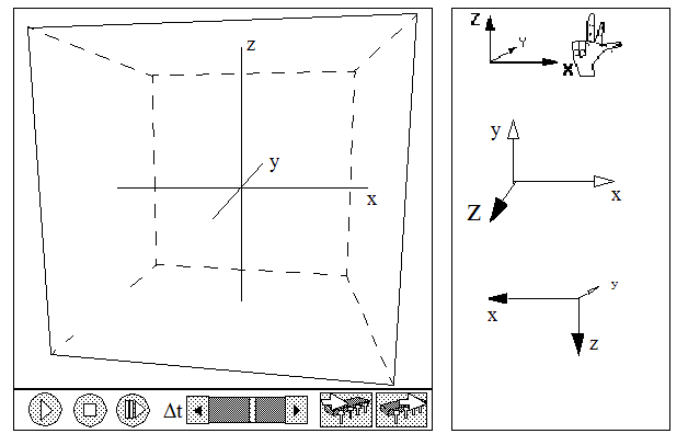
Fig. 2.2.:xyz-axis under differen perspectives
As long as this sequence is respected, any orientation in space is equivalent as demonstrated with the three possibilities to the right.
As default view within Java-xyz the position shown above has been selected. In this default position the positive x-orientation points to the right, the positive y-orientation points to the back, and the positive z-orientation points upwards.
Coordinates in space
Units of length
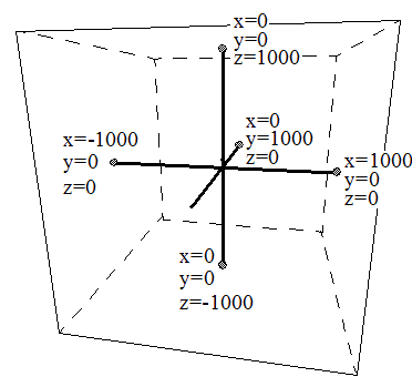
Fig. 2.3.:xyz-Cube with axis and coordinates
The length of the three axes x, y, and z from the origin to the walls of the JavaXYZ cube is divided in 1000 units. The length of each edge of the cube is therefore equal to 2000 units
The actual length of this unit on the screen corresponds to about 0.1 mm. However, since you are dealing with a simulation there is no reason, not to think of such a unit as representing a larger length, for instance 1mm. In this case the JavaXYZ cube would represent a cubic volume with an edge length of 2m.
Positions
Based on a system of rectangular coordinate axes, each position in space can be identified by three numbers, called coordinates. To do so, it is necessary to define the positive orientations of x, y and z by following the right-hand-rule described above.
A specific position within this cube is described by three numbers, the x-, y- and z-coordinates in this sequence.
Example:
P(1000, -1000, 1000)
indicates the upper right corner of the front side of the cube.
To get used to this structure and its different coordinates it may be useful invest some time for exercising.
Below you find a list of positions for particles within the xyz-cube. Can you determine in thought where these particles should be located?
P (1000, 0, 0); P (1000; 1000; 1000); P (-1000; 0; 0); P (-500; -500; -500);
P (+500; +500; +500)
>To place a particle at a wanted position there are two possibilities: You can either use the "Particle Management" window (at A in fig.2.4) where you can place a particle at a predefined location (at B and C).
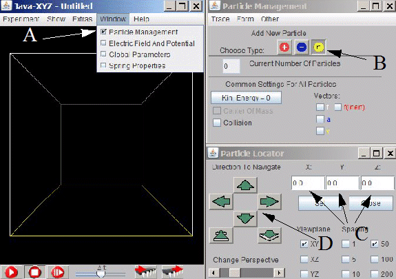
Fig. 2.4.:To set a particle, the Particle Management window has to be selected (A)
The type of the particle can be selected at B. Its position can be determined
either by entering numbers at C or by activating the green arrows (D).
The second possibility is to open the "Particles Inspector" window of a particle (which should have been placed before) by selected the particle with the right mouse button (see fig.2.5) and then the ,Edit Particle" submenu. The "Particles Inspector" window offers the possibility to enter or change the coordinates numerically. When doing so each individual input has to be finished by hitting the "enter" key
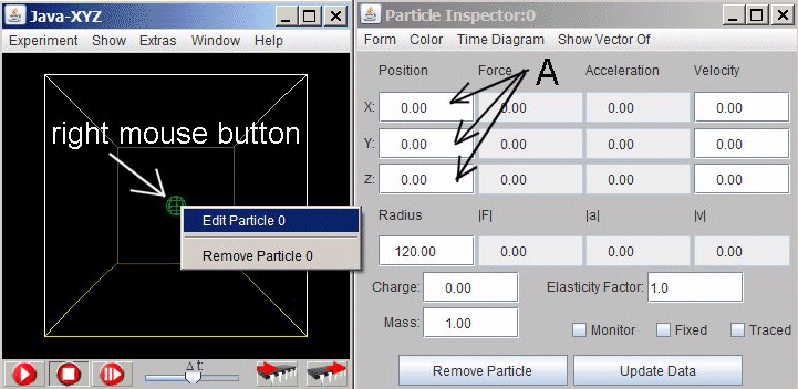
Fig. 2.5.:XYZ-cube with the Particle Inspector window where the position
of the particle can be entered numerically (A)
zurück zur Startseite
Fig. 2.1.: Main simulation window with control buttons
User Interface
The cube and its content can be rotated by clicking with the left mouse button down within the cube and moving the mouse.If in addition the shift button is down, the cube can be moved. With the ctrl-button down the cube can be zoomed in and out.
The buttons
allow to start or stop the simulation. To advance the simulation by single step the step button
has to be activated. The slider of Δt allows to change the speed, with which the simulation is displayed.
Activating the save button will keep a copy of the actual state of the simulation in memory, which can be recalled to the screen at any time by activating the recall button
Right-angled coordinate system
Sequence of the axes
Within the cube of Java-XYZ a right-angled coordinate system is used to define positions and directions.
By convention the sequence of the axes for such a right-angled coordinate system has been determined by the so-called "right-hand-rule". The thumb points in the direction of x, the forefinger points in the direction of y, and the middle finger in the direction of z.
Fig. 2.2.:xyz-axis under differen perspectives
As long as this sequence is respected, any orientation in space is equivalent as demonstrated with the three possibilities to the right.
As default view within Java-xyz the position shown above has been selected. In this default position the positive x-orientation points to the right, the positive y-orientation points to the back, and the positive z-orientation points upwards.
Fig. 2.2.:xyz-axis under differen perspectives
Coordinates in space
Units of length
Fig. 2.3.:xyz-Cube with axis and coordinates
The length of the three axes x, y, and z from the origin to the walls of the JavaXYZ cube is divided in 1000 units. The length of each edge of the cube is therefore equal to 2000 units
The actual length of this unit on the screen corresponds to about 0.1 mm. However, since you are dealing with a simulation there is no reason, not to think of such a unit as representing a larger length, for instance 1mm. In this case the JavaXYZ cube would represent a cubic volume with an edge length of 2m.
Positions
Based on a system of rectangular coordinate axes, each position in space can be identified by three numbers, called coordinates. To do so, it is necessary to define the positive orientations of x, y and z by following the right-hand-rule described above.
A specific position within this cube is described by three numbers, the x-, y- and z-coordinates in this sequence.
Example:
P(1000, -1000, 1000)
indicates the upper right corner of the front side of the cube.
To get used to this structure and its different coordinates it may be useful invest some time for exercising.
Below you find a list of positions for particles within the xyz-cube. Can you determine in thought where these particles should be located?
P (1000, 0, 0); P (1000; 1000; 1000); P (-1000; 0; 0); P (-500; -500; -500);
P (+500; +500; +500)
>To place a particle at a wanted position there are two possibilities: You can either use the "Particle Management" window (at A in fig.2.4) where you can place a particle at a predefined location (at B and C).
Fig. 2.4.:To set a particle, the Particle Management window has to be selected (A)
The type of the particle can be selected at B. Its position can be determined
either by entering numbers at C or by activating the green arrows (D).
The second possibility is to open the "Particles Inspector" window of a particle (which should have been placed before) by selected the particle with the right mouse button (see fig.2.5) and then the ,Edit Particle" submenu. The "Particles Inspector" window offers the possibility to enter or change the coordinates numerically. When doing so each individual input has to be finished by hitting the "enter" key
Fig. 2.5.:XYZ-cube with the Particle Inspector window where the position
of the particle can be entered numerically (A)
zurück zur Startseite
Fig. 2.3.:xyz-Cube with axis and coordinates
Fig. 2.4.:To set a particle, the Particle Management window has to be selected (A)
Fig. 2.5.:XYZ-cube with the Particle Inspector window where the position
of the particle can be entered numerically (A)