back to Circuits (home page)
Capacitor properties of electric circuits
5.1. Properties of a capacitor
In principle a capacitor consists of two relatively large metallic foils - or isolating plates with metallic surfaces - separated by a rather thin layer. This separating layer is often filled with some isolating material to prevent any electric conduct between the two internal metallic surfaces.
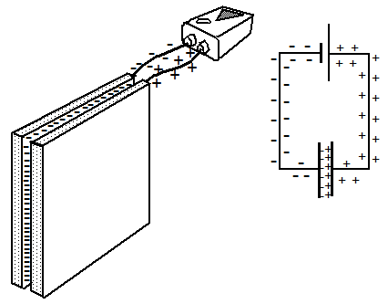
Fig. 13: Basic construction of a capacitor, connected to a power source
Significantly increased charge density between the plates
compared to the density on the wires
If a power source is connected with a capacitor by two conductive wires, electrons are moved towards one of the two internal surfaces due to the driving force of the source. On the opposite surface the same number of atoms will no longer be neutral but show up as positive charge.
Because the separating layer between the two metallic surfaces is rather thin the attracting Coulomb forces between these opposite charges are increased and start to play an important role. These forces reduce the mutually repelling forces on each internal surface of the capacitor, and this implies that the driving force of the power source can create a much higher density of surface charges on these internal surfaces until again an equilibrium is reached between the driving force of the power source and the repelling forces of the compressed surface charges.
The thinner the separating layer the larger is the attracting Coulomb force across this layer. This implies an increased reduction of the mutually repelling Coulomb forces on each surface and an enlarged density of surface charges as a result of an applied voltage.
The number of additional charges on the surface of a normal conductor is rather small because the repelling forces between such charges are rather large so that it needs a small density of surface charge to reach an equilibrium with the driving force of a power source.
The electrons on the surface of normal conductors show only a very small elastic behavior, they can hardly be compressed.
The charges on the internal surfaces of a capacitor, however, attract each other and are therefore much more elastic and compressible compared to a normal conductor.
Fig. 13: Basic construction of a capacitor, connected to a power source
Significantly increased charge density between the plates
compared to the density on the wires
5.2. Capacitor and capacitance
The amount of charge q which can be compressed into a capacitor until an equilibrium is reached is proportional to the applied voltage V.
In other words: Q/V is a characteristic constant for each capacitor. It is called capacitance and is indicated as C. C = Q/V.
The unit of capacitance is 1 Farad, abbreviated 1 F, in honour of the English physicist Michael Faraday (1791-1867).
A capacitance of 1 F indicates, that for an applied voltage of 1 V a unit charge of 1 Q = 6,2 1018 electrons will flow into a capacitor. This is a large number for a small voltage and can normally not be realized. The capacitance of normally available capacitors lay in the range of μF to nF (10-6 to 10-9F).
5.3. Charging and de-charging of capacitors
It seems obvious to assume that the charging of a capacitor will take some time until a stationary state is reached. A large number of electrons have to be brought to the inner surface of the capacitor until the resulting density is high enough to block any further input of electrons.
It seems further reasonable to assume that the time period T for reaching this stationary state will depend on the seize of the capacitance C and the resistance R of the conducting wires. The larger C and R the larger T.
The seize of the charging current is not constant. It is decreasing in time because of the increasing amount of Coulomb forces which are opposing the driving force of the power source.
As proven by theory and experiment the time dependence of the charging current follows an exponential function with negative exponent.
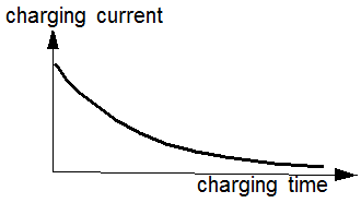
Abb. 14: Time dependence of a capacitor charging current
Abb. 14: Time dependence of a capacitor charging current
5.3. Simple electric circuits with and without circuit capacitance
Usually the most simple electric circuit is seen as a system where a power source and a resistor are connected by two conducting wires.
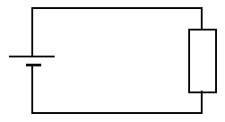
Fig. 15: Circuit diagram of a simple electric circuit
This is an idealization because it is neglected that the surfaces of the wires form some kind of capacitor with a small but always non-zero capacitance.
As long as the focus is set only on stationary states without asking for a causal relation between such states, this kind of representation is sufficient.
However, for a more detailed consideration it is necessary to include the capacitance of the wires.
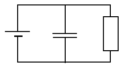
Fig. 16: Equivalent circuit diagram of a simple electric circuit,
including the capacitance of the conducting wires
As a consequence and depending on the seize of this capacitance the transition of one to the next stationary state will be more or less retarded.
In the following a simulation program will be presented where the capacitance of the wires is strongly increased so that the transition processes become visible.
The main reason for this is a didactical one. The fact should be made very clear that nature does not jump from one state to another but that there exists always a causal relation between two stationary states in form of specific transition processes.
Fig. 15: Circuit diagram of a simple electric circuit
Fig. 16: Equivalent circuit diagram of a simple electric circuit,
including the capacitance of the conducting wires
back to Circuits (home page)